Industrial Automation
BIW Fixture Design: From Concept to Manufacturing-Ready Drawings

By Alex A
Head of Engineering


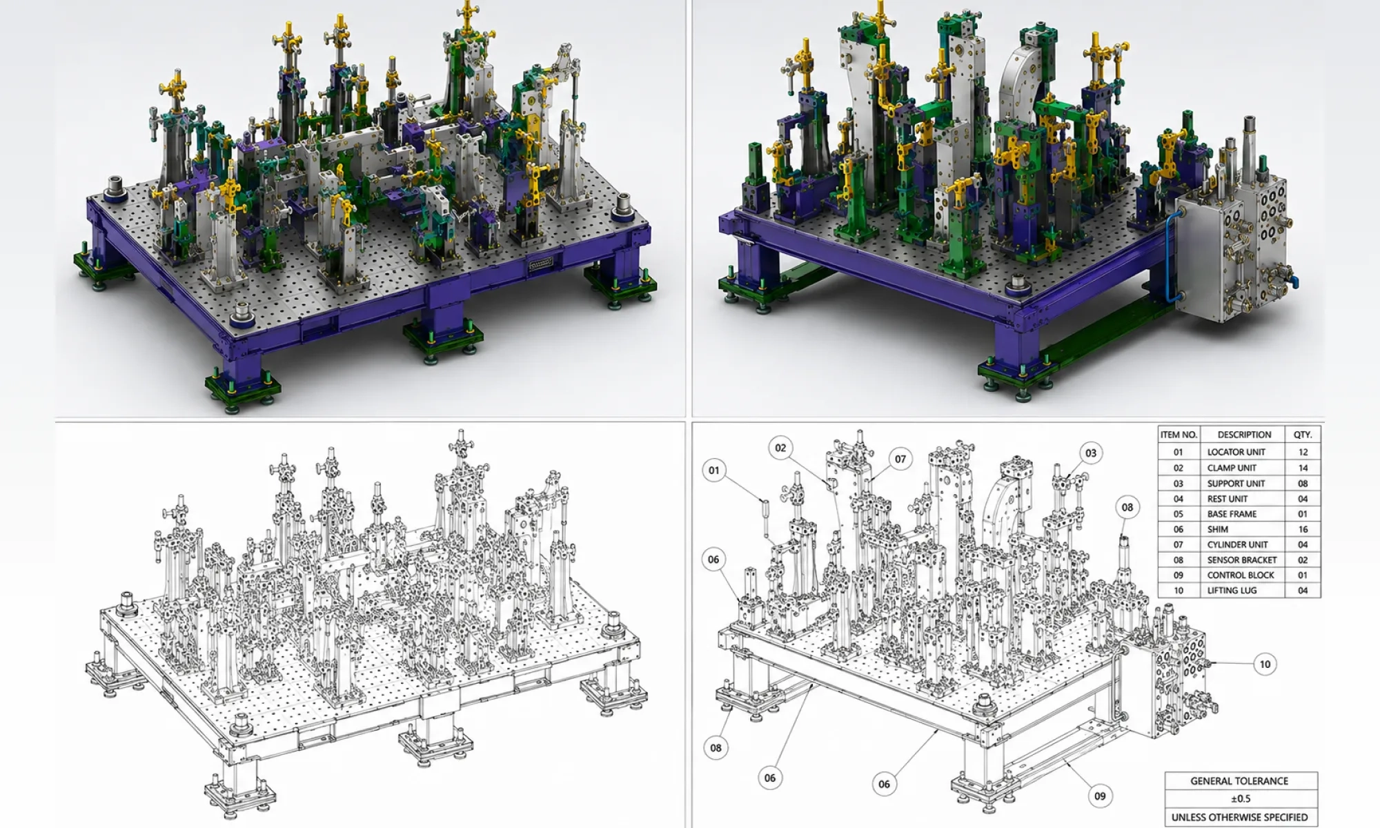
In automotive manufacturing, the body-in-white (BIW) is assembled from multiple sheet-metal components that need to come together with tight positional accuracy. These parts are welded and joined before the body moves on to painting and final assembly. Keeping every component in the right position throughout this process is important for consistent fit, alignment and dimensional accuracy.
BIW fixtures provide that control. They locate, support and clamp components during welding and assembly. The fixture also needs to leave enough room for robots, weld guns, operators and inspection.
A well-designed fixture therefore has to balance accurate positioning, accessibility, repeatability, and practical production requirements. It should also be practical to manufacture, operate, and maintain throughout its production life.
In this guide, we cover the key design considerations, common challenges, design process, and deliverables involved in developing a Body in White fixture from concept to manufacturing-ready drawings.
What is a BIW fixture?
A BIW fixture is a tooling assembly used to position and hold vehicle body components during welding, assembly, or inspection. It combines different tooling units to locate the part accurately and keep it stable throughout the operation.
Common components and tooling units include:
- Clamp units: Hold the panel securely against the locating points.
- Pin units: Use round and diamond locator pins to accurately position the component.
- Rest units: Support the panel and help prevent movement or deflection. These may include Mylar blocks, rest pads or NC blocks.
- Slide and dump units: Move clamps or other tooling elements when space or access is limited.
- Riser and bracket units: Position and support tooling components at the required height and location.
- Shims and adjustment elements: Allow fine adjustment of tooling positions and compensate for tolerances.
- Sensors and pneumatic components: Support automated functions such as part detection and clamp operation.
The arrangement of these units depends on the component geometry, locating requirements (datum scheme), welding process, automation requirements and production sequence. For example, a fixture used for robotic welding may have very different requirements from one used for inspection or manual assembly.
This is why fixture design starts with understanding the part, process and production environment, rather than simply selecting clamps and locators.
Types of BIW fixtures used in automotive manufacturing
BIW fixtures are designed for different stages of body assembly, and each type has a specific role. The design can vary considerably depending on the component, joining process, automation level and accuracy requirements.
Geo fixtures
Geo fixtures are used in geo stations to accurately locate and hold BIW components during initial assembly and welding. The critical spot welds defined in the process datasheet or CSV are carried out at this stage using geo-spot fixtures.
These initial welds help establish and maintain the required geometry and position of the components before the assembly moves to subsequent welding operations. The fixture therefore needs to provide accurate, repeatable positioning while leaving enough access for the welding process.
Re-spot fixtures
Re-spot fixtures receive pre-welded BIW sub-assemblies from geo stations and hold them in position for the remaining secondary and finishing spot welds.
They need to maintain the established geometry while providing access to the required weld locations.
Welding fixtures
Welding fixtures are used to hold and position components during welding, including welding processes beyond the spot-welding operations carried out in geo and re-spot stations.
For example, fixtures may be designed for MIG, TIG or arc welding, depending on the component and joining process. In automotive welding fixture design, the focus is on getting the right balance of stable clamping, weld-gun access, robot clearance and smooth welding sequence while avoiding potential collisions.
Assembly fixtures
Assembly fixtures locate and hold components in the required position during automotive assembly. They help maintain accurate alignment while parts are joined together. Their design needs to provide secure positioning, easy component access and smooth loading and unloading during the assembly process.
Sealing fixtures
Sealing fixtures are used to locate and hold BIW components during sealing operations. They keep the parts in the required position while sealant is applied.
The design should provide consistent positioning and clear access for the sealing equipment.
Hemming fixtures
Hemming fixtures are used to locate and support closure panels such as doors, hoods, and decklids during hemming. They keep the panels stable as the edges are folded and formed.
Accurate positioning helps achieve consistent panel fit, gaps and alignment.
Manual assembly / SSW fixtures
Manual fixtures are used for operator-led assembly and stationary spot welding (SSW) operations. They help locate and hold components in the required position during joining.
The fixture should be easy to load and operate while providing accurate, repeatable positioning.
Checking fixtures
Checking fixtures are used to verify whether a component or assembly meets the required dimensional and positional specifications.
Their locating strategy is particularly important because the fixture itself becomes the reference for inspection.
Drilling fixtures
Drilling fixtures are used to locate and hold BIW components during drilling operations. They help maintain the required hole position and keep the component stable during machining.
The design should provide accurate locating, stable support and clear access for the drilling tool.
Gripper fixtures
Grippers or handiling fixtures are used with robots to grip, hold, and transfer BIW components between stations. They are a type of end-of-arm tooling (EOAT) mounted on the robot wrist.
The design needs to provide secure handling while maintaining the required part position during transfer. Weight, gripping points, robot reach and collision clearance also need to be considered.
Key design considerations for BIW fixtures
A BIW fixture has to do several jobs at once. It must hold components securely, maintain their position, provide access for welding and automation, and remain practical to build and maintain.
This makes fixture design a series of engineering decisions. Here are a few key considerations that directly affect accuracy, cycle time, and production reliability.
1. Datum (reference) and locating strategy
The datum references and locating points establish how the BIW component is positioned in the fixture. Locators, rest points and other tooling elements are arranged around these references to achieve accurate and repeatable positioning.
Where specific clamp locations or clamping requirements are provided as part of the project inputs, they should also be incorporated into the fixture layout.
The goal is to hold the component securely without over-constraining it or affecting access for welding, assembly or automation.
2. 3-2-1 Locating principle
The 3-2-1 locating principle is commonly used in BIW fixtures to position a component and control its six degrees of freedom.
Three locating points establish the primary plane, two locate the secondary plane, and one controls the remaining direction. This provides stable and repeatable positioning while helping prevent over-constraint.
3. Clamping strategy and sequence
Clamps hold the component against its locating points throughout the operation. Their position and sequence matter.
Clamping should provide enough force to keep the part stable without deforming it. The arrangement should also allow easy loading and unloading while keeping clamps clear of robots, weld guns, and other tooling.
4. Weld gun and tool accessibility
A fixture can locate a part accurately and still create problems if the weld gun cannot reach the required points.
The design needs sufficient clearance around weld locations and suitable approach paths for the welding equipment. Clamp arms, locators, supports, and other fixture components should not interfere with the welding operation.
5. Robot reach and collision clearance
In automotive automation, fixtures play an important role in how smoothly a robotic station operates. They must stay within the robot’s working range while providing clear access for robots and welding tools. Good fixture design helps avoid interference and supports repeatable movement and efficient cycle times.
6. Positional accuracy and repeatability
A fixture should position the component the same way every time. Locator accuracy, fixture rigidity, part variation, and clamping stability all affect this repeatability. BIW welding fixture design should also account for part and fixture tolerances so normal variations do not affect the required assembly accuracy.
7. Operator and maintenance access
Production fixtures need to be accessible, not just accurate.
Operators should be able to load and unload components without unnecessary difficulty. Maintenance teams also need access to clamps, sensors, pneumatic components, and replaceable tooling elements when adjustments or repairs are required.
8. Fixture weight and rigidity
The fixture needs enough rigidity to resist movement and deflection during operation. At the same time, excessive structure can make the fixture unnecessarily heavy and difficult to handle.
The design should provide the required stiffness without adding material where it does not contribute to fixture performance.
9. Modular and standardized design
Using standard components and modular fixture elements can simplify design, fabrication, maintenance, and future modifications.
It also makes replacement parts easier to source and allows the fixture to be adapted when the product or process changes.
10. Cycle time considerations
Fixture design can influence how quickly a station completes its operation.
Clamping and unclamping should be efficient, while loading, unloading, welding access, and robot movement should not introduce unnecessary delays. Small improvements at the fixture level can matter when the same operation is repeated throughout a production shift.
Industry standards used in BIW fixture design
BIW fixture designs are rarely developed in isolation. They need to meet the requirements of the vehicle program, manufacturing process, and customer.
The exact requirements vary by OEM and project, but several standards and guidelines commonly influence fixture design:
- NAAMS standards: North American Automotive Metric Standards (NAAMS) provide standardized specifications for automotive tooling components. Using standard components can improve consistency and make fixture design, fabrication and maintenance easier.
- OEM-specific standards: OEMs often define their own requirements for fixture construction, tooling components, CAD models, tolerances, drawings and documentation. These requirements should be considered from the early design stage.
- GD&T requirements: Geometric Dimensioning and Tolerancing (GD&T) defines how dimensional and geometric requirements are communicated on engineering drawings. In BIW fixtures, it helps control critical locating and mounting features and maintain the required positioning accuracy.
- Applicable safety standards: Fixtures used in automated or robotic cells need to meet the relevant machinery and robot safety requirements. ISO 10218 is one of the key standards for the safety of industrial robots and robotic systems.
- Robot manufacturer guidelines: For robotic BIW applications, the fixture also needs to work with the selected robot and tooling. Factors such as payload, mounting, working range and robot movement can influence the fixture design. VDI 2861 can be considered when defining industrial robot characteristics.
- Customer-specific documentation requirements: Customers may have their own requirements for drawing templates, naming conventions, BOM structure, revision control, file formats and design release documentation. Defining these requirements early helps avoid changes later in the project.
Common BIW fixture design challenges and how to solve them
BIW fixture design can look straightforward on a CAD screen. The real challenges often appear when the fixture has to work with the part, robot, weld gun, operator, and production process at the same time.
Here are some of the issues designs need to address.
Inaccurate part positioning
The component may not sit in the correct position if the locating points do not match the part geometry or datum requirements. This can affect alignment during welding and assembly.
Solution: Define the datum (reference) strategy early and position locators based on the part geometry and required tolerances.
Fixture deflection
A fixture can move or deflect when clamping forces are applied or during welding. This can affect the position of the component and reduce repeatability.
Solution: Provide sufficient structural support and stiffness while avoiding unnecessary weight.
Weld gun accessibility issues
Limited weld gun access is one of the common BIW welding challenges. The fixture must hold the component securely while leaving enough space for the weld gun to reach each required weld point. Clamps, locators, and supports should not interfere with the tool or its approach path.
Solution: Check weld locations and tool approach paths during design and maintain adequate clearance.
Robot collision risks
In an automated station, the robot needs enough space to move around the fixture and reach the required positions. Fixture components can create interference if this is not considered early.
Solution: Validate the robot envelope and check potential collision points before finalizing the fixture design.
Excessive clamp count
Adding more clamps may seem like a simple way to improve stability, but it can make the fixture heavier and more complex. It can also increase maintenance requirements.
Solution: Optimize clamp locations and use only the clamping points needed for stable and repeatable positioning.
Difficult maintenance access
Clamps, sensors, pins and pneumatic components may need adjustment or replacement during production. Poor access can make these tasks more difficult and time-consuming.
Solution: Provide sufficient clearance around serviceable components and consider maintenance access during the design stage.
Late product design changes
BIW components can change during product development. A change in part geometry or mounting points may then require modifications to the fixture.
Solution: Use modular construction and standardized components where practical to make future changes easier.
Pneumatic routing challenges
Pneumatic hoses need to move with the fixture without getting caught, damaged, or interfering with other components. Poor routing can also make maintenance harder.
Solution: Plan pneumatic routing as part of the fixture design and keep hoses clear of moving components, heat sources, and operator areas.
Step-by-step BIW fixture design process
BIW fixture design starts with understanding the part and process requirements. The design then moves through concept development, detailed modeling, validation and documentation before the fixture is released for manufacturing.
- Review project inputs and product data: Start with the BIW CAD model, drawings, weld information, customer standards, and process requirements. This gives the design team a clear understanding of what the fixture needs to achieve.
- Develop the locating and clamping strategy: Define the part datums, locating points, supports, and clamps needed to position and hold the component accurately and repeatably.
- Develop the fixture concept: Create the initial fixture layout and arrange the base structure, locators, clamps, supports, and other tooling components around the component.
- Validate accessibility and automation: Check robot reach, weld-gun access, tool clearances, loading and unloading and potential interference before moving into detailed design.
- Complete the detailed 3D design: Develop the complete fixture model with the required structure, brackets, standard components, clamps, sensors, and pneumatic components.
- Review the design and prepare documentation: Review the fixture for accuracy, manufacturability, accessibility, and project requirements. Then prepare the assembly drawings, detail drawings, GD&T information, and BOM.
- Final design release: Once the design and documentation are reviewed and approved, the final fixture package is released for fabrication, assembly and production.
Planning a new automated or semi-automated station? Explore our Automation Machine Design Services for custom machine and robotic cell design support.
When to outsource BIW fixture design
Outsourcing can help automotive manufacturers and engineering teams add design capacity when fixture workloads increase or projects need specialized support.
- Limited internal design capacity: When several fixture and tooling projects are running at once, external support can help with 3D modeling, detailing, drawings, and BOM development without expanding the permanent team.
- New vehicle programs and multiple fixtures: New programs can bring a large number of fixtures, grippers, and tooling assemblies within tight timelines. Additional engineering resources can help manage the workload and keep the project on schedule.
- Need for manufacturing-ready documentation: If you already have the fixture concept or 3D model, an engineering partner can take it forward with detailed fabrication drawings, assembly drawings, part drawings and related documentation.
- Specialized BIW engineering support: When a project requires experience in BIW fixture design, tooling, welding automation, robot integration and manufacturing detailing, an external engineering team can provide the required expertise and capacity.
Need BIW fixture design support for your next automotive project?
Need a new fixture designed? Modifying an existing one? Or simply need more engineering capacity?
Sedin Engineering can help.
Our engineers support BIW fixture design, 3D modeling, tooling detailing, manufacturing drawings, BOM developmentLink and welding automation design.
Have the concept ready? We can take it through detailed design and manufacturing documentation.
Starting with BIW data and process requirements? We can support the fixture design from concept to final release.
Need extra engineering capacity for an ongoing project? We can work alongside your team.
Explore our Industrial Automation Services or contact us to discuss your requirements.
Related Blogs


Assembly Line Automation in 2026: Top Industries Driving Demand
Learn what assembly line automation is, which industries use it most, which processes are automated first, and how to choose the right automation partner for your factory.


Automation in Manufacturing Industry: Improve Efficiency and ROI
Manufacturing automation helps cut costs by up to 40%, improve productivity, and give manufacturers faster ROI with safer, more efficient operations.


Top 7 Industrial Automation Companies in the USA (2026 Guide)
Who’s shaping industrial automation in 2026? Explore the biggest U.S. players and understand which types of projects each is best suited for.