Product Design
Heat Exchanger Design: Thermal, Mechanical and Manufacturing Considerations

By Alex A
Head of Engineering


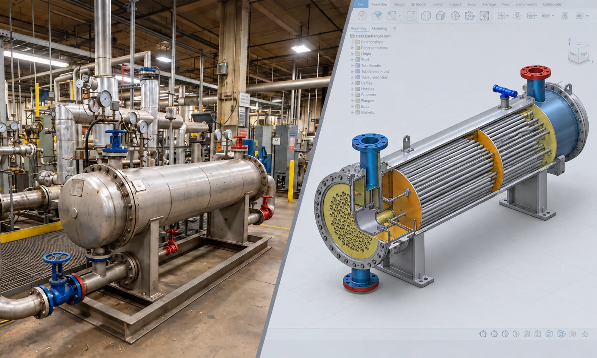
A heat exchanger can meet its required heat duty and still run into problems in actual operation.
Pressure drop may be higher than expected. Fouling can reduce heat transfer. Vibration can affect tube life. And a design that works well on paper may be difficult to manufacture, maintain or modify later.
Getting these details right starts with understanding the application and choosing an appropriate heat exchanger design. From there, thermal and mechanical requirements need to work together to create equipment that performs efficiently.
This guide covers the fundamentals of heat exchanger design, including the main types of heat exchangers, the design process, material and mechanical considerations, common design challenges and approaches to redesigning existing equipment.
What is heat exchanger design?
Heat exchanger design is the process of developing equipment that transfers heat between two fluids.
The goal is not simply to achieve the required heat transfer rate. The design must also operate within pressure drop limits, withstand operating temperatures and pressures, comply with applicable standards and remain practical to manufacture and maintain.
As a result, heat exchanger design involves a series of engineering decisions that affect performance, reliability and cost. The following sections explain the information engineers need before starting a design and the key stages involved in developing a manufacturing-ready heat exchanger.
What information is required before designing a heat exchanger?
Before thermal calculations begin, we need a clear understanding of the process requirements and operating conditions. Missing or inaccurate design inputs can lead to incorrect sizing, performance issues, redesigns and increased project costs.
The key information required for heat exchanger design includes:
- Process requirements: The first point is understanding the thermal duty of the heat exchanger. This includes the required heat load, flow rates, inlet and outlet temperatures and the desired thermal performance.
- Fluid properties: Fluid characteristics have a direct impact on heat transfer and pressure drop calculations. It's important to evaluate properties like density, viscosity, specific heat, thermal conductivity and fouling tendencies.
- Operating conditions: Design pressure and temperature influence material selection, wall thickness, component sizing and compliance requirements. Both normal operating conditions and design conditions should be considered during the design phase.
- Pressure drop limits: While maximizing heat transfer is important, excessive pressure drop can increase pumping costs and affect overall system performance. Allowable pressure drop is therefore a key design input.
- Installation and space constraints: Available installation space often influences heat exchanger type, orientation, dimensions, nozzle locations and maintenance accessibility. These constraints should be identified early in the project.
- Applicable codes and standards: Many heat exchangers must comply with standards like ASME Section VIII, API requirements or customer-specific specifications. Identifying these requirements early helps avoid costly design changes later.
With these inputs defined, design engineers can begin evaluating heat exchanger configurations and selecting the most suitable design for the application.
Selecting the right heat exchanger type
Not every application requires the same type of heat exchanger. The right choice depends on the operating conditions, fluid characteristics, heat duty, available space, maintenance requirements and project budget.
An unsuitable type can affect heat transfer performance, increase pressure drop and make maintenance more difficult. It can also add unnecessary costs to the project.
Selecting the right heat exchanger early helps ensure the equipment can handle the required heat duty and operating conditions while meeting the practical needs of the application.
The table below summarizes some of the most commonly used heat exchanger types.
| Heat Exchanger Type | Applications | Key Advantages |
|---|---|---|
| Shell and tube | Process industries, power generation, oil & gas | Handles high pressures and temperatures, easy to maintain |
| Plate | Food processing, HVAC, chemical processing | Compact design and high heat transfer efficiency |
| Air-cooled | Locations with limited water availability | Eliminates the need for cooling water |
| Double pipe | Small-capacity applications | Simple design and easy installation |
| Coaxial | Heat pumps, refrigeration, water-source systems | Compact design, efficient heat transfer, simple construction |
While several heat exchanger configurations are available, shell-and-tube heat exchangers remain the most widely used for industrial applications. Their ability to handle a broad range of operating pressures, temperatures, and process fluids makes them suitable for many industries.
Heat exchanger design process
Once the heat exchanger type has been selected, the detailed design process begins. Some of the most important heat exchanger design considerations include thermal performance, pressure drop, mechanical integrity, manufacturability, maintainability and cost.
While the specific requirements vary from project to project, the overall design process generally follows a similar steps.
Step 1: Thermal design and heat exchanger sizing
Thermal design establishes the performance requirements and overall size of the heat exchanger.
The process begins with key operating data, including flow rates, inlet and outlet temperatures, fluid properties, heat duty, fouling tendencies and allowable pressure drop. Using methods like Log Mean Temperature Difference (LMTD) and Effectiveness-NTU (Number of Transfer Units), the required heat transfer area can be determined.
These thermal calculations establish the foundation of the overall design. They help determine how much heat needs to be transferred and guide decisions about the exchanger’s size, configuration and allowable pressure drop.
But getting the required heat transfer area is only part of the thermal design. The exchanger also needs to achieve the required heat transfer without creating excessive pressure loss or operating problems. This means evaluating several design variables, including:
- Flow arrangement (counterflow, parallel flow or crossflow)
- Tube diameter and tube length
- Tube layout and pitch
- Number of tube and shell passes
- Fluid velocity
- Baffle spacing
- Fouling allowances
These variables are closely connected. For example, increasing fluid velocity can improve heat transfer, but it also increases pressure drop and pumping requirements. Similarly, reducing baffle spacing can improve shell-side heat transfer, but it can also increase pressure loss.
The goal is to achieve the required thermal performance while balancing hydraulic and operational considerations.
While the basic principles of heat transfer remain the same, each heat exchanger type has its own thermal design considerations. Shell-and-tube heat exchanger design involves tube layout, pass arrangement and baffle design. Plate heat exchangers focus on plate and channel configuration, while coaxial heat exchangers focus on efficient heat transfer in compact spaces with acceptable pressure drop.
Step 2: Mechanical design
The next step is mechanical design. This is where the thermal concept is developed into equipment that can be manufactured, installed and operated safely throughout its service life.
The design must withstand operating pressure, temperature, thermal expansion and mechanical loads while meeting applicable codes and standards.
The components considered depend on the type and configuration of the heat exchanger. For a shell-and-tube exchanger, for example, the design may include the shell, tubes, tube sheets, baffles, nozzles and supports.
Design for manufacturing (DFM) is also considered at this stage. Weld accessibility, fabrication tolerances, material availability, assembly and inspection access are reviewed to ensure the design is practical to manufacture.
Key heat exchanger mechanical design considerations include:
- Pressure containment requirements
- Thermal expansion and differential growth between components
- Flow-induced vibration and tube support requirements
- Nozzle loads and connection design
- Structural integrity under operating and installation conditions
- Accessibility for inspection, cleaning and maintenance
- Compliance with standards like ASME and TEMA
Addressing them during the design stage helps reduce the risk of failures, downtime and costly modifications later.
Step 3: Material selection
Material selection determines how well a heat exchanger withstands its operating conditions and how long it will remain efficient.
The material is selected based on:
- Process fluid and its corrosiveness
- Operating temperature and pressure
- Corrosion and erosion risks
- Fouling conditions
- Fabrication and inspection requirements
- Project cost
For general applications, carbon steel and stainless steel are commonly used.
When the heat exchanger handles corrosive fluids, high temperatures, high pressures or aggressive chemicals, materials like duplex stainless steel, titanium, copper alloys or nickel-based alloys may be more suitable.
The goal is to select a material that provides the required strength, corrosion resistance and service life without adding unnecessary cost.
Step 4: Design validation and engineering analysis
In demanding industrial heat exchanger design projects, additional engineering analysis is performed to validate design assumptions before fabrication begins.
Computational Fluid Dynamics (CFD) can be used to evaluate:
- Flow distribution
- Dead zones and recirculation regions
- Temperature distribution
- Pressure losses
Finite Element Analysis (FEA) can be used to assess:
- Structural stresses
- Thermal stresses
- Deflection
- Fatigue-sensitive areas
These analyses help identify potential issues early in the design process and reduce the risk of performance problems after installation.
Step 5: Manufacturing documentation and design for fabrication
Once the design is finalized, it needs to be translated into detailed documentation for manufacturing and assembly. The drawings and models should also reflect practical manufacturing requirements considered during the design process.
The final engineering package includes:
- 3D CAD models
- General arrangement drawings
- Fabrication drawings
- Tube sheet and component drawings
- Weld details
- Bills of materials (BOMs)
- Thermal and mechanical design reports
Before the package is released for manufacturing, details such as weld accessibility, fabrication tolerances, inspection requirements, material availability and assembly constraints are reviewed to ensure the design is practical to manufacture. This helps reduce fabrication issues and rework while ensuring the finished heat exchanger matches the approved design and performs as intended.
For additional guidance on manufacturing-ready documentation, see our Technical Documentation Checklist.
Common heat exchanger design challenges and how to address them
Industrial heat exchanger design requires balancing thermal performance with mechanical and operational requirements. Addressing common challenges early can help avoid performance issues, excessive maintenance and costly modifications later.
Fouling
Deposits can build up on heat transfer surfaces, reducing heat transfer efficiency and increasing pressure drop and cleaning requirements.
Design approach: Consider fluid properties, flow velocity, fouling resistance and cleaning requirements. Provide adequate access for inspection and cleaning, particularly for applications with high fouling potential.
Excessive pressure drop
A higher fluid velocity can improve heat transfer but also increases pressure drop. Excessive pressure loss can increase pumping or fan power and operating costs.
Design approach: Balance tube diameter, tube length, number of tube passes, shell-side flow path and baffle spacing with the allowable pressure drop.
Corrosion and material degradation
Process fluids and operating conditions can cause corrosion, leakage and premature component failure if the material is not suitable for the application.
Design approach: Select materials based on fluid composition, temperature, pressure, corrosion mechanisms and expected service life. Depending on the application, materials may include carbon steel, stainless steel, duplex stainless steel, titanium or nickel-based alloys.
Tube vibration
Flow-induced vibration causes tube wear, fatigue and eventual failure, particularly in shell-and-tube heat exchangers.
Design approach: Evaluate tube support, baffle spacing, flow velocity and flow-induced vibration to keep vibration within acceptable limits.
Thermal expansion
As temperatures change, heat exchanger components can expand and contract at different rates. Restricting this movement can create excessive stresses in tubes, tube sheets, shells and connected piping.
Design approach: Use appropriate clearances, flexible connections, expansion joints or suitable support arrangements to accommodate thermal movement.
Manufacturability and maintenance access
A heat exchanger may perform well thermally but still be difficult to fabricate, inspect, clean or repair.
Design approach: Consider weld accessibility, tube removal, inspection points, cleaning access, component replacement and assembly requirements before finalizing the design.
Heat exchanger design standards and codes
Heat exchanger designs must often comply with industry standards, regulatory requirements and customer specifications. These requirements can influence material selection, pressure-containing parts, fabrication, inspection, testing and documentation.
Some commonly referenced standards include:
- ASME Section VIII: Applies to pressure vessels and can govern the design, fabrication, inspection and testing of pressure-containing heat exchanger components.
- TEMA: The Tubular Exchanger Manufacturers Association provides guidelines for the mechanical design, fabrication, inspection and maintenance of shell-and-tube heat exchangers.
- API 660: Commonly referenced for shell-and-tube heat exchangers used in petroleum and petrochemical applications.
- API 661 / ISO 13706: Cover air-cooled heat exchangers used in refinery and petrochemical applications.
- Customer and regional requirements: Projects may also have specific requirements for materials, welding, non-destructive testing (NDT), quality documentation and certification. Equipment supplied to European markets may also need to meet the Pressure Equipment Directive (PED).
The applicable standards should be identified early in the design process. This helps ensure the heat exchanger meets the required safety, performance and compliance requirements and reduces the chance of redesign later.
When should a heat exchanger be redesigned or upgraded?
Not every project requires a heat exchanger to be designed from scratch. In many cases, modifying or upgrading an existing design can be a more practical way to improve performance, increase capacity, or address changing operating requirements.
Over time, process conditions change, production demands increase, and equipment ages. As a result, a heat exchanger that once met performance requirements may no longer operate as efficiently or reliably as intended.
Common signs that a heat exchanger needs a redesign or upgrade include:
- Reduced thermal performance despite operating under similar conditions.
- Excessive pressure drop leading to higher pumping requirements and energy costs.
- Increasing fouling rates that require frequent cleaning and maintenance.
- Recurring tube failures, leakage or corrosion-related issues that affect reliability.
- Capacity limitations that restrict production growth.
- Changes in process conditions, including different fluids, temperatures, pressures or flow rates.
- Rising maintenance costs and reduced equipment reliability.
- Obsolete equipment or materials that are difficult to maintain or replace.
- New safety, compliance or customer requirements that the original design was not intended to meet.
In many cases, targeted design modifications can improve thermal performance, extend service life, increase capacity or reduce operating costs without replacing the entire heat exchanger.
Planning a new heat exchanger or redesigning an existing one?
The right design approach can improve heat exchanger performance, reliability and manufacturability while helping avoid costly changes later. Whether you are developing a new exchanger, increasing capacity or addressing performance issues, the design needs to match the actual process and operating conditions.
With your process requirements or existing exchanger design, Sedin Engineering can evaluate the requirements and develop the detailed design needed for your project.
Have a heat exchanger to design or redesign? Explore our Heat Exchanger Design & Detailing Services to discuss your requirements with our engineering team.
Related Blogs


User Manual vs. Maintenance Manual: What You Need for Your Industrial Product Launch
Learn the difference between user and maintenance manuals for industrial products. Discover when you need both and why professional technical writing is important.


BESS Design: Safe, Efficient & Scalable Energy Storage
Learn how smart BESS design improves safety, efficiency and scalability. Explore key insights to build reliable, manufacturable energy storage systems.


New Product Development: From Concept to Manufacturing
NPD involves several stages, from defining requirements and developing concepts to detailed design, prototyping, validation and manufacturing preparation.