Welding Automation
Automated Spot-Welding Cell Design for Automotive Door Reinforcement
The customer brings over 40 years of expertise specializing in the design and manufacture of fully integrated, totally automated systems, stand-alone assembly machines, specialised machines, and automated & secondary equipment, various welding cells and stand-alone machines.
Scope
The client sought us to design and develop a fully automated Spot-Welding Cell for the door reinforcement part of the 4-door car variant.
The scope included:
- Design of a NAAMS-compliant welding cell
- Design of welding fixture mounted on a rotary indexing table
- Provision for two additional fixtures on the rotary table to support future model variants (as a future scope)
- Integration of industrial robot from KUKA (customer-scope)
- Integration of a X-gun from Obara (customer-scope)


Challenge
Desinging an automatic spot welding cell came with several technical challenges, including:
- Future Fixture Provision: Designing a welding fixture on a rotary table while allowing space for two additional fixtures in the future, without increasing the current cell size.
- LH and RH Part Handling: Designing a single automated spot welding cell capable of handling both LH and RH door reinforcement parts without adding fixture or layout complexity.
- NC Locator Design: Designing NC locators to suit the part profile as per NAAMS standards, while selecting spatter-resistant materials to ensure long service life.
- Operator Ergonomics: Ensuring easy and safe manual loading and unloading by considering operator reach, loading height and part orientation.
- Compact Cell Layout: Maintaining a compact welding cell design with minimum floor space after integrating the customer-supplied robot and welding gun.
Solution
As part of our industrial automation services, we followed a structured design approach to deliver a reliable and efficient automated spot welding cell. The process started with a clear understanding of the part, welding requirements, and production needs, followed by careful equipment and layout planning.
All designs complied with NAAMS standards and were validated through virtual simulation and DFMEA to ensure consistent weld quality and repeatable performance.
Here’s our step-by-step design approach
1. Process Analysis and Cell Layout
Our team started the design work with detailed analysis of the door reinforcement part geometry, weld locations and LH/RH variants. Based on this study, the cell layout was designed to keep the footprint compact while ensuring the robot could reach all required weld points. The rotary table position was planned to meet current manufacturing requirements and to allow easy addition of fixtures in the future.
2. Robot and Welding Equipment Integration
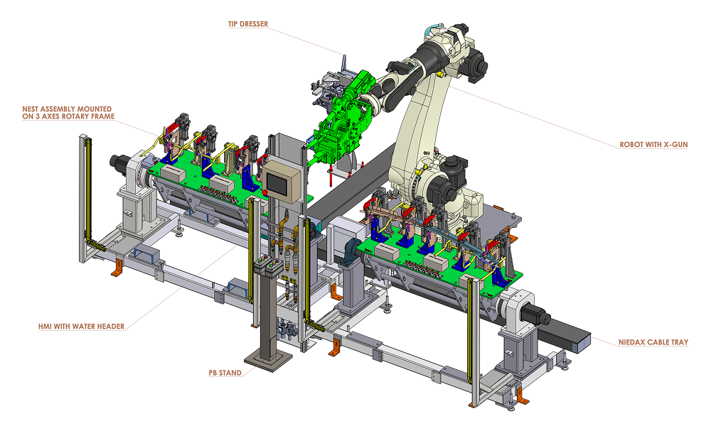
The automated spot welding cell was designed around 6-axis robot from KUKA and X-type welding gun from Obara. Our solution focused on integrating this equipment into a compact and efficient cell layout while ensuring full access to all weld locations.
To support reliable welding operation, the design included:
- Provision for auxiliary systems like tip dresser, weld timer, and standard water-cooling units
- Use of Niedax cable trays for safe and organized cable routing
- Virtual simulation to confirm robot reach, welding gun accessibility, and collision-free motion before finalizing the design
3. Rotary Table and Fixture Design
Once the overall cell layout was finalized, the fixture design started with defining the rotary table concept, which acts as the main platform for holding and positioning the parts during welding. A rotary table with 3-axis fixture positioning was selected to ensure accurate location and smooth indexing during operation.
Rotary table design included:
- 3-axis fixture positioning to allow accurate adjustment and alignment
- Fixtures and counterweights arranged in a triangular skeleton layout to avoid interference and maintain balance during rotation
- Provision for stable mounting of current and future fixtures
Once the rotary table concept was finalized, the fixture and clamping systems were designed for secure part holding during welding.
Fixture and locator design highlights:
- Profile-matched NC locators designed as per NAAMS standards ensured accurate part location while preventing surface damage.
- Copper material was selected for resting units to reduce weld spatter buildup and improve service life.
- Locating units were provided with adjustment in all three directions, enabling precise setup and repeatable part positioning.
- Clamping cylinders were used to securely hold the component.
- LH and RH fixture assemblies were placed adjacent to each other, allowing both variants to be handled efficiently within the same cell.
- The fixture design achieved repeatability within ±0.05 mm, ensuring consistent and reliable weld quality.
The welding fixture design was kept compact and flexible, allowing both LH and RH variants to be processed within the same cell without increasing the overall footprint. Locator and clamp positions were planned to ensure clear welding gun access and smooth, collision-free robot movement.
4. Ergonomics and Safety
- Fixture height and orientation were optimized for operator comfort and safe manual loading/unloading.
- Safety features like light curtains, interlocked maintenance doors, and emergency stops were included in line with key standards such as ISO 12100, ISO 10218, and ISO 13849-1, along with the end customer’s safety requirements.
5. Design Validation and Risk Mitigation
To ensure the spot welding cell design was robust and manufacturing-ready, Design Failure Modes and Effects Analysis (DFMEA) was carried out. This helped identify and address potential risks related to fixture location, clamping sequence, part loading, and robot motion at an early stage, reducing the chances of rework or downtime later.
Additionally, a virtual cell simulation was performed to validate weld accessibility, robot paths and cycle time feasibility. By validating these aspects early in the design phase, the solution minimized shop-floor risks and provided a reliable foundation for safe robot operation and consistent production performance.
Value and Benefits
The rotary table was designed with provision for two additional fixtures, enabling future model or variant additions with minimal impact on the existing cell layout.
Early design validation significantly reduced shop-floor risks during installation and ramp-up, helping avoid rework and unplanned delays.
High fixture and locator repeatability resulted in stable weld locations and consistent weld quality throughout production.
The welding cell met the required operation cycle time, which enabled smooth throughput without compromising safety or process stability.
The compact cell layout minimized floor space usage while still allowing provision for future fixtures and part variants.
Related Case Studies


Robotic MIG Welding Cell for Boiler Lid
Discover how our team designed a robotic MIG welding system with dual fixtures and Yaskawa robots, boosting precision, throughput, and weld consistency.


Automated Ultrasonic Welding Cell Design
Advanced ultrasonic welding cell designed for automotive rear step pads, boosting weld accuracy, efficiency, and safety with cutting-edge robotic and quality monitoring systems.


Semi-Automated Leak Testing Machine Design
Improved productivity and ensured precise leak testing for cylinder heads with our advanced automated solution, trusted by top manufacturers.