Material Handling
Battery Pack Assembly Line Design and Automation
The client is a Canada-based automation company that provides turnkey industrial automation systems and custom equipment. They manufacture custom automation systems for industries like automotive, pulp and paper products and consumer packaging.
Scope
The client sought us to design a complete end-to-end battery pack assembly line for AGV applications, covering the full manufacturing flow from pouch cell preparation to final pack testing.
Project scope included:
- Define mechanical concepts for each station, including fixtures, tooling, and mechanisms for cell handling, stacking, tab forming, welding, enclosure assembly and testing
- Define the automation strategy (manual, semi-automatic, and fully automated stations)
- Support two battery module variants (1S6P and 9S2P) using RFID-based variant selection
- Plan the full line layout and material flow for smooth production movement
- Integrate key processes like plasma treatment, laser welding, thermal event containment, and inline inspection
- Provide full 3D modeling of stations and tooling
- Deliver complete manufacturing drawings for fabrication and assembly
- Plan for future expansion stations to allow upgrades without redesigning the line
All designs were developed to meet the client’s specifications, production targets, safety standards, and applicable compliance requirements, ensuring the line was ready for implementation and future expansion.
Challenge
Designing this battery pack assembly line came with several challenges, mainly due to delicate pouch cell handling and the strict safety requirements of lithium battery assembly. Key challenges included:
- Design Constraints: The line layout had to fit within available floor space while maintaining operator access, safety zones, smooth material flow, and space for future expansion.
- Pouch Cell Handling & Stack Repeatability: Pouch cells are fragile, so the design needed precise handling, controlled stacking, and repeatable compression without damaging the cells.
- Multi-Variant Support: Supporting two battery variants (1S6P and 9S2P) required RFID-based process control, variant-specific pallets/tooling, and error-proofing across multiple stations.
- Tab Processing & Welding Readiness: Tab trimming, cleaning, bending, and height control had to be consistent to ensure stable laser welding and low-resistance electrical connections.
- Traceability & Inline Quality: The line needed barcode/RFID traceability and inline inspections to detect defects early and support quality reporting and audits.


Solution
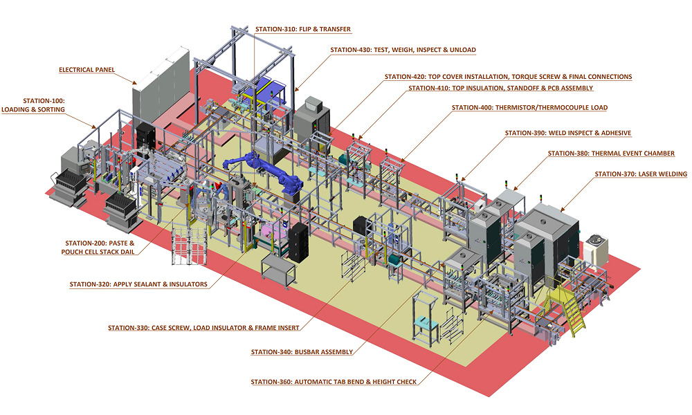
We developed the complete design package for a 21-station battery pack assembly line as part of our industrial automation services, covering the full process from pouch cell preparation to final testing and inspection.
The line was designed as a modular, station-based system for easy scaling and future upgrades. It handled two battery variants (1S6P and 9S2P) using RFID (Radio Frequency Identification) so each station automatically ran the correct process for the selected variant.
It was engineered to assemble lithium-ion pouch cells stacked into modules. Busbars were used for electrical connections, and laser welding was used for tab joining. Since the packs were built for AGV applications, the design focused on high repeatability, strong safety controls and reliable electrical performance for industrial duty cycles.
The battery assembly line followed five main stages: cell preparation and sorting → stacking and compression → insulation and enclosure assembly → joining and welding → inspection and end-of-line testing.
Our approach automated the most critical quality processes while keeping selected stations operator-assisted where flexibility was required.
Below are the key process stages and design highlights developed for this battery pack assembly line.
1. Cell preparation, tab trimming & voltage sorting
To ensure only good cells moved forward in the assembly line, we designed a cell preparation and inspection station with cassette-based loading and robotic handling.
At this stage, the system:
- Trimmed the cell tabs automatically
- Measured cell voltage using pogo-pin contacts
- Sorted cells into multiple lanes based on voltage range
- Rejected any out-of-spec cells automatically
- Logged all results using barcode/RFID traceability
To keep the line running smoothly, we designed an automatic replacement cell retrieval feature. If a cell was rejected downstream, the system automatically pulled a qualified replacement cell from the correct voltage-sorted lane and fed it back into the process.
2. Automated sealant dispensing & controlled pouch cell stacking
For pouch cell stacking, we designed a servo-indexed dial system. This allowed the cells to be assembled into the required module configuration with stable cycle time and consistent assembly results.
This stage included:
- Robotic paste/sealant dispensing at predefined locations
- Plasma cleaning of tabs to improve joining consistency
- Barcode-based polarity and orientation checks
- Controlled tab bending before placement
- Servo-based compression after each stacking cycle
To improve repeatability, the stacking fixture was designed to step down after every layer, keeping a constant working height for robotic placement. Stack height and compression were verified using servo position feedback and laser sensing.
This ensured consistent stacking alignment and controlled compression, which are critical for pouch cell module quality.
3. Pallet handling, flipping & variant-based transfer
Once stacking was complete, the modules moved into a pallet-based transfer system. We designed the pallet handling concept to ensure smooth transport and repeatable positioning across all stations.
The system used lift-and-stop mechanisms for accurate pallet positioning, along with controlled pallet rotation to match the required variant orientation. RFID-based identification was integrated to track each unit through the full process.
Custom pallets were designed with locating features to keep the modules stable and correctly aligned during welding and inspection processes.
Robots were used where required to transfer assemblies between stations. An automatic tool changer allowed the robot to switch grippers for different components and battery variants. This reduced manual handling, improved positioning accuracy and maintained full traceability throughout the line.
Note: To support both battery variants (1S6P and 9S2P), separate pallets were designed for each configuration. During changeover, the operator swapped the pallet, and the HMI updated the process settings to match the selected variant.
4. Insulation and sealant application (hybrid automation)
We designed a hybrid insulation and sealant station to ensure both sides of the assembly received proper coverage without overcomplicating automation.
Here’s how it worked:
- The robot loaded the assembly into a fixture
- A pneumatic lift-and-rotate mechanism lifted the part and rotated it 180°
- Insulation material and adhesive were applied automatically to the top side
- The unit was indexed for operator access
- The operator flipped the assembly to complete bottom-side application
This approach ensured consistent insulation coverage on both sides while maintaining takt time.
5. Enclosure assembly & busbar installation with polarity verification
For enclosure and busbar integration, we designed an assembly workstation that balanced operator flexibility with automated error-proofing.
The station included:
- Locating guides for correct case positioning
- Torque-controlled fastening for consistent tightening
- Busbar alignment features for repeatable placement
- Robotic polarity and placement verification before final tightening
This reduced polarity errors and supported multi-variant assembly without adding unnecessary automation complexity.
6. Plasma torch surface treatment
To ensure consistent busbar welding and reliable adhesive bonding, we integrated a plasma torch surface treatment station into the line design. The plasma torch was mounted on a servo-driven gantry system to ensure accurate positioning and repeatable surface coverage.
This step improved surface cleanliness and activation, which helped reduce variation in joining quality.
7. Tab forming, flattening & height control
We designed a dedicated tab forming station to ensure the cell tabs were shaped correctly before welding. This station bent and flattened the tabs to the required position and height, ensuring consistent alignment across every build. The system used servo-controlled multi-axis motion with variant-based tool selection to support both battery configurations.
8. Laser welding cell with thermal monitoring
For tab-to-busbar joining, we designed a laser welding cell with gantry-based positioning and controlled clamping to ensure consistent weld quality. Thermal monitoring was integrated to detect abnormal heat buildup during welding.
If the temperature exceeded the defined limit, the unit was automatically diverted to a safety containment station. Normal units continued through the line as usual.
9. Thermal event containment chamber
To address lithium battery manufacturing safety requirements, we designed a dedicated thermal containment chamber capable of isolating overheating or fire scenarios.
The chamber included:
- Automatic door closure and isolation
- Sand drop suppression system
- Smoke evacuation through exhaust extraction
- Independent operation logic to safely complete containment cycles
This chamber improved overall line safety and reduced risk during overheating or fire incidents.
10. Weld inspection & post-process dispensing
To verify weld quality before final assembly, we integrated a weld inspection station using a camera system with controlled lighting. The inspection verified weld presence, position, and surface condition.
To verify weld quality before final assembly, we integrated a weld inspection station using a camera system with controlled lighting. The inspection verified weld presence, position, and surface condition.
After inspection, we integrated a precision dispensing system to apply sealant at predefined locations to protect the weld joints, improve insulation and secure assembly. The dispenser used a progressive cavity pump on a servo-driven gantry. This ensured accurate bead placement and controlled dispense volume.
11. Sensor installation & top assembly integration
For final electrical integration, we designed operator-assisted workstations for:
- Thermistor/thermocouple installation
- Insulation placement
- Standoff installation
- PCB mounting and fastening
Torque reactor arms and controlled fastening tools were included to improve ergonomics and fastening consistency. Manual installation was used where automation was not practical due to small wires and variable cable routing.
12. Final cover installation & end-of-line validation
We engineered the final assembly stage to ensure every unit was mechanically complete and electrically verified before release.
The end-of-line validation included:
- Torque-controlled fastening for consistent clamping force
- Weight verification to detect missing components
- HIPOT testing for insulation integrity
- DCIR testing for electrical performance verification
- Lift-assist unloading for safe handling
All test results were digitally logged and linked to the unit ID, ensuring full traceability.
13. Future expansion and variant support
To support long-term scalability, we included reserved expansion stations in the line layout so new processes could be added later without major redesign.
We also designed a dedicated sub-assembly station for insulation pad tape application to improve consistency for the 1S6P configuration.
14. Safety & standards considerations
The battery assembly line was designed with safety and compliance in mind. The overall system concept was developed in accordance with key industrial safety standards, including ISO 12100, ISO 13849-1, and IEC 60204-1, along with North American electrical and control panel requirements specified by the client.
Overall, the battery pack assembly line was designed to deliver safe, repeatable battery assembly with strong quality control and flexibility to support future product variants and process upgrades.
Value and Benefits
Improved battery pack consistency by controlling pouch stacking, compression and tab forming to support stable welding and assembly.
Reduced defects and rework through voltage-based cell sorting, inline inspections, weld verification, controlled dispensing and end-of-line electrical testing.
Improved manufacturing safety by integrating guarded automation zones, safety interlocks and a dedicated thermal event containment chamber for overheating scenarios.
Enabled multi-variant assembly (1S6P and 9S2P) using RFID tracking, automatic variant selection and built-in error checks to reduce assembly mistakes and simplify changeovers.
Accelerated implementation and future upgrades through a modular layout, reserved expansion stations and fabrication-ready documentation to support faster production ramp-up.
Related Case Studies


Semi-Automated Drilling and Routing Machine Design for EV Battery Panels
Learn how our custom-designed semi-automated drilling and routing machine improves EV battery panel machining efficiency, flexibility and quality.


Bottle Capping Assembly
Designed a high-speed bottle filling and capping machine, boosting production efficiency to 80 bottles per minute and ensuring consistent quality.


Clip Assembly Automation for Riveting & Sealant Application
Boosted efficiency by automating riveting and sealant application for clips used in standing seam roofing.