Oil & Gas
Design Engineering of Process Tanks and Custom Supporting Equipment
A leading provider of engineering and modular construction services in the Oil and Gas industry sought assistance in designing two process tanks. They also required support in developing the piping systems and custom equipment tailored to these tanks.
Scope
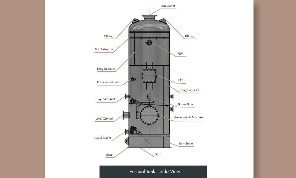
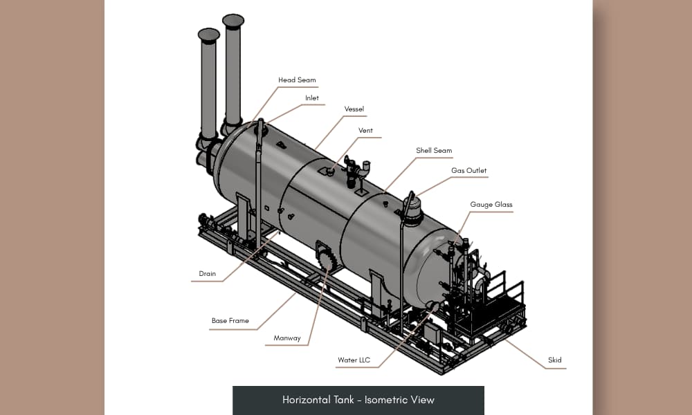
Our team was involved in the detailed engineering and design of vertical and horizontal oil, gas, and water process tanks, along with vessels and associated piping systems.
The team prepared general arrangement drawings, production drawings of process equipment and piping systems. The 2D drawings, 3D models, and fabrication drawings were submitted to the client for periodic approval and reviewed against their drawing checklists.
We drafted the following equipment for the client and prepared the actual drawings after client review:
Heater Treater – Heats crude oil and facilitates the separation of oil from water. The separated components are diverted through dedicated piping systems connected to the vessel.
Surge Vessel – Neutralises fluctuations in water velocity and prevents pipe ruptures and valve failures.
Gas Scrubber – Removes entrained liquids and solid impurities from gas streams, ensuring cleaner gas and protecting equipment.
We incorporated the following scope during the design process:
- Process Equipment Design: Customise the tank models and develop design templates to ensure they align with the client's calculations. Design safe and efficient oil, gas, and water separation tanks with ready-to-install skids. Create detailed lifting plans for safe installation and assembly.
- Skid Systems Integration: Design portable vessel skids as part of a closed process circuit, incorporating both inlets and outlets to improve support for the tanks and streamline installation at the oil processing plant, gas treatment facility, and wellhead processing facility.
- Mechanical Integrity and Nozzle Design: Ensure the nozzles can withstand the flow velocity and the temperature of the fluids and gas vapour at the terminal points.
- Structural and Code Compliance: Ensure the design of the tank components, structural detailing of the vessels and piping systems adhere to the relevant ASME code and API standards.
Challenge
The following constraints were considered while preparing the drawings and models:
- Restricted Flow: Misalignment of pipelines at inlet and outlet terminal points created excessive stress on piping connections, leading to restricted flow efficiency. Limited accessibility caused difficulty in operation and maintenance.
- Leakage: Potential leakage issues due to uneven placement of nozzles led to installation errors. Misaligned connections caused stress on the welded components, eventually forming micro-cracks.
- Client Specs vs Code requirements: Aligning tank designs with both the client’s specifications and material requirements prescribed in ASME and API standards.
- Temperature Considerations: Preparing the structure of the tanks for multiphase handling, including continuous flow of hot fluids and vapours. Possible stress on the support structures of the tanks and distortion of the shell and nozzles due to thermal expansion or contraction.
Solution
The 2D drawings and 3D models contained plan and elevation views of tanks, vessels, and piping systems.
Our team’s meticulous design approach enabled proper segregation of oil, water, and gas in the process tanks, strengthened piping support systems, maintained equipment quality standards and reduced potential equipment damage.
- Enhanced Structural Alignment: Simplified the installation process of the vessel skid by reducing the height of piping lines of the horizontal tank and saddle support. Aligned nozzles with existing piping systems across the plants. Enabled access to the pipelines for maintenance access and system integration.
- Improved Structural Strength: Facilitated a leak-resistant seal by securing flanges around nozzles. Improved structural robustness using reinforcement pads to protect against cracks and improve load distribution inside the vessels.
- Quality Control and Validation: Highlighted client specifications and ASME requirements in a shared workflow. Reconciled the specs through dedicated technical meetings to ensure material compatibility.
- Mitigated Temperature effects: Addressed thermal expansion effects by optimising saddle supports (horizontal tank) and skirt with baseplate configurations (vertical tank) to allow controlled structural movement. Selected suitable materials such as nickel alloys, titanium, Fiber Reinforced Plastic (FRP), etc., to withstand thermal and process conditions and minimise shell and nozzle distortion.
Value and Benefits
Eased installation process during fabrication through careful design optimisation. Incorporated client-supplied dimensions and material requirements to enhance the design.
Designed 3D models of the tanks and their supporting components using Autodesk Inventor to achieve accuracy in fabrication-level production drawings.
Reduced installation time errors up to 85% through improved configurations. Shared the design files in a standardised and flexible workflow, allowing changes wherever necessary.
Minimised process-related leakages of oil, gas, and water through meticulous selection and design. Integrated fittings and design components in compliance with ASME B16 standards.
Related Case Studies


Diesel Storage Tank Design
Expansion of Pelican Point Terminal with the design and construction of three 30,000m³ diesel storage tanks, ensuring safety, compliance, and operational efficiency.


Optimising Efficiency for a Beer Plant
Enhanced piping design boosts efficiency, production, and cost savings for a beer manufacturing plant.