Food & Beverage
Screw Conveyor and Rendering Equipment Design for Australian Abattoir Equipment Supplier
The client is an Australia-based supplier of processing equipment for the rendering and abattoir industries. They manufacture material conveying systems including elevators and multi-screw material handling bins for meat rendering applications.
Scope
The scope covered the detailed design, 3D modeling and engineering drawings for equipment used in rendering and abattoir applications, including:
- Conveyor systems
- Drainers
- Ducting
- Platforms
- Tank agitators
The work included developing 3D models and assemblies, integrating components and drive mechanisms and preparing detailed fabrication drawings, BOMs and purchased-part lists for manufacturing and assembly.

Challenge
Developing detailed meat rendering equipment design from existing G.A. layouts presented several engineering challenges. The main challenges included:
- Coordinating different equipment: Conveyors, drainers, ducting, platforms and tank agitators had to fit within the overall layout while maintaining the required interfaces and connections between equipment.
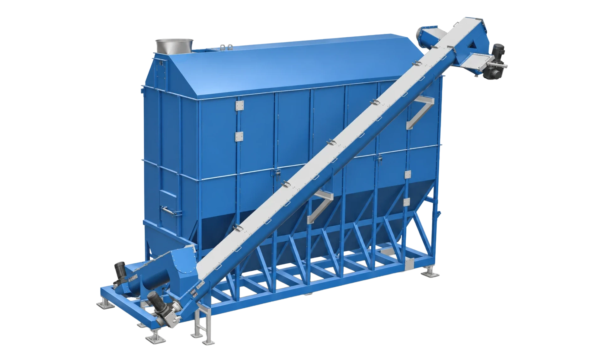
- Handling different conveyor configurations: The project included horizontal and inclined screw conveyors, with top- and bottom-driven arrangements and different casing configurations. Each design required the right component arrangement, supports, clearances, and drive integration.
- Integrating drives and components: Drive mechanisms and purchased components had to be incorporated into the assemblies while maintaining proper fit, connections, clearances, and access for assembly and maintenance.
- Maintaining fabrication accuracy: Material specifications, dimensions, tolerances and weld details had to remain consistent across assemblies and individual components to support accurate fabrication and assembly.
- Managing parts and documentation: The different equipment assemblies involved numerous components and purchased parts, making accurate BOMs and parts lists important for procurement and manufacturing.
- Meeting application requirements: The equipment had to be developed according to the customer's project-specific standards and applicable requirements for rendering and abattoir applications.
Solution
Sedin Engineering supported the customer with meat rendering equipment design, developing existing G.A. layouts into detailed 3D models, assemblies, and manufacturing drawings. The scope covered screw conveyors, drainers, ducting, platforms and tank agitators for rendering and abattoir applications.
Our engineers reviewed the layouts, recommended design improvements, integrated components and drive mechanisms and developed the equipment in Autodesk Inventor for fabrication and assembly.
1. Equipment design review and layout coordination
The team reviewed the customer's G.A. layouts to understand the equipment arrangement, available space, material movement, and interfaces between adjoining systems.
The review covered conveyor configurations, component placement, drive locations, structural supports and clearances. Based on the findings, the engineers recommended design improvements and aligned the conveyor layouts with supporting equipment.
Transportation and handling requirements were also considered. Where necessary, component dimensions and assembly arrangements were reviewed to accommodate transport limitations.
2. Design considerations for rendering and abattoir equipment
The equipment designs were developed around the customer's operating requirements and project specifications for meat rendering and abattoir applications.
The team considered material selection, equipment accessibility, safety, and interfaces between assemblies. Applicable project standards and regulatory requirements were also considered, including ANSI B11.19, ISO 14120 and relevant USDA and FDA requirements, where applicable.
3. Screw conveyor design and configuration
Screw conveyor design was a key part of the project. Our engineers developed different configurations to suit the equipment layout and material movement requirements.
The designs included:
- Horizontal screw conveyors for conveying material along level sections.
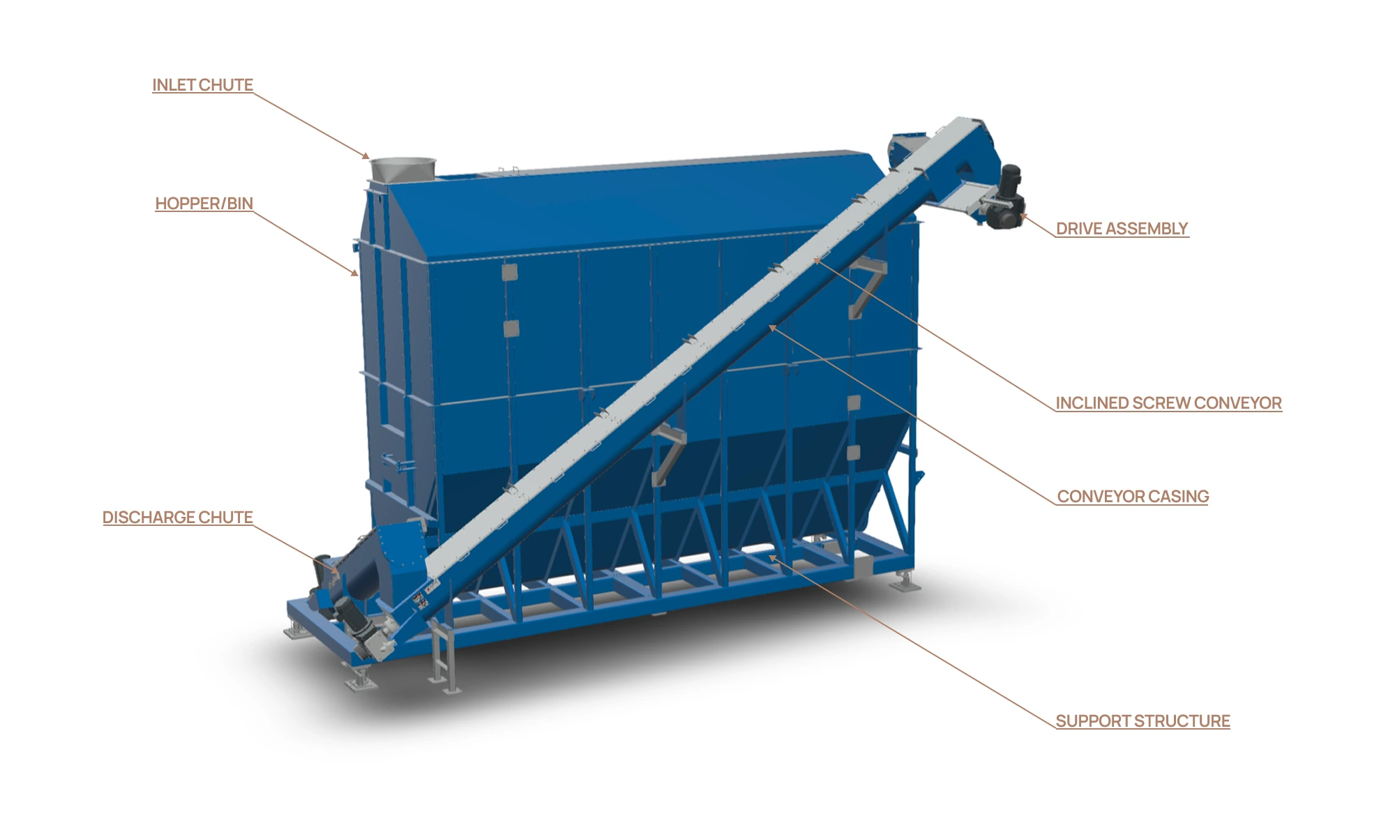
- Bottom-driven inclined screw conveyors with the drive positioned at the lower end.
- Top-driven inclined screw conveyors with the drive positioned at the upper end.
Four casing configurations were incorporated: U-trough, flared, wrap-around, and circular. The selection depended on the conveyor arrangement and layout requirements.
Depending on the configuration, the assemblies included screw flights, shaft pipes, hanger bearings, drives, drive supports, support frames, covers, chutes and slide gates. These components were coordinated with supporting structures and adjoining equipment, with attention to clearances and drive interfaces.
4. 3D modeling and assembly development
Using Autodesk Inventor, Sedin developed detailed 3D models and assemblies for the screw conveyors and associated rendering equipment.
Individual components were modeled and assembled to evaluate their fit within the overall equipment arrangement. We considered:
- Component fit and clearances
- Interfaces between adjoining equipment
- Structural supports and mounting arrangements
- Assembly and maintenance access
The 3D models helped identify potential fit and interface issues early in the design process and served as the basis for preparing detailed manufacturing drawings.
5. Material selection and fabrication planning
We selected mild steel and Grade 304 stainless steel based on the equipment application and customer requirements. Material specifications were inlcuded in the 3D models and fabrication drawings to guide manufacturing.
.The team also considered welding and assembly requirements, including sealant at the inlet and discharge chutes. Component dimensions were checked against the galvanizing tank capacity, with design adjustments considered where needed.
6. Drive and purchased-component integration
Drive mechanisms and purchased components were incorporated into the equipment assemblies based on their function, mounting requirements and available space.
For the conveyor systems, the engineers coordinated drive positions with the conveyor configuration and supporting structure. Mounting locations, connection interfaces and accessibility were reviewed to ensure the components could be accommodated within the developed assemblies.
7. Manufacturing drawings and engineering documentation
Using the coordinated Autodesk Inventor models and assemblies, Sedin developed detailed fabrication, component and assembly drawings for the rendering equipment.
The engineering deliverables included:
- Fabrication and component drawings with dimensions and tolerances
- Assembly drawings showing component arrangements and interfaces
- Material specifications and welding details
- Bills of Materials (BOMs) and purchased-part lists
The completed drawing package gave the customer the details needed to move forward with fabrication and assembly. If you're developing similar rendering or food processing equipment, Sedin Engineering’s 3D modeling and 2D drafting services can help turn your equipment layouts into detailed models and manufacturing drawings.
Value and Benefits
Sedin helped the customer move from existing G.A. layouts to detailed, fabrication-ready equipment designs, reducing the engineering time needed to take projects forward.
By handling 3D modeling, assembly development, detailing and engineering documentation, Sedin reduced the workload on the customer's internal engineering team.
Reviewing equipment interfaces, clearances, component placement and drive arrangements during design helped identify potential issues before fabrication, reducing design rework.
Detailed fabrication drawings, BOMs, purchased-part lists, material specifications and weld details gave the manufacturing team clear information for procurement, fabrication and assembly.
The additional engineering capacity allowed the customer to manage different rendering and abattoir equipment requirements without having to handle the entire design workload internally.